6 : The Microphone
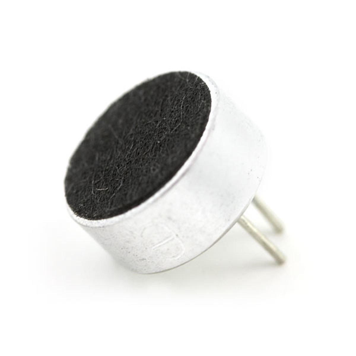
What you can see here is an electret microphone. Often some components will require a whole circuit for them to work. You could make these circuits yourself, which would take quite of time and energy but will offer you all the flexibility to design the circuit how you like or ....

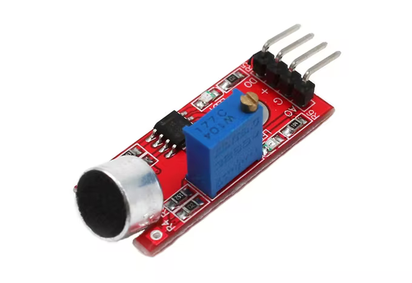
.... you could use a development module like this KY-038 which does it for you and offers conveniently labeled pins to get going quickly.
The electricity in the LED and the potentiometer was both the power and the signal. Most of the time these are separate.
In this case “+” is “power in” so you will need to connect it to the 5V pin of the Arduino which is a pin constantly outputting 5 volts.
”G” is the “power out” so you need to connect it to the GND pin of the arduino.

The other two pin carry “signals”, these are electrical currents which are about information and not about power.
The “D0” pin will give current whenever the microphone senses past a certain sound level. You can adjust the threshold level by turning the screw sitting on top of the little blue box.
What is that mysterious little blue box?
What is that mysterious little blue box?
There is a tiny green LED to make the setting up of the threshold easier, this LED will turn on if you are above the threshold so to adjust it you can use the procedure below.
- If it’s not lit up, lower the threshold by turning the screw clockwise on the little blue box until it lights up then very gently go back counter-clockwise and stop as soon as it turns off.
- If it’s not lit up, lower the threshold by turning the screw clockwise on the little blue box until it lights up then very gently go back counter-clockwise and stop as soon as it turns off.
Exercise 9
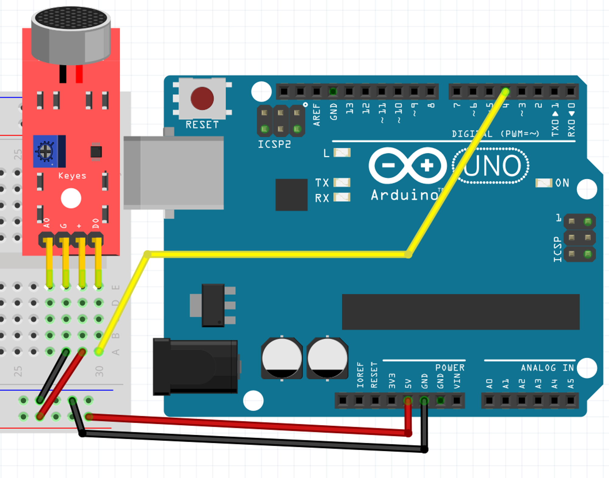
Given everything you’ve read so far, can you wire the mic to the Arduino and write the code to see the signal of “D0” in the monitor?
Circuit answer

Code answer
void setup() {
  Serial.begin(9600);

    //remember, we have to tell if digital pins are either inputs or outputs
  pinMode(7,INPUT);
}

void loop() {
  Serial.println( digitalRead(7) );
}
If D0 gives digital signals, you might be able to guess how A0 works. A0 will give you a tension which will vary intensity with the different audio frequencies it will pick up. The screw on the blue box will help you set the sensitivity of the mic. Because the blue box have an effect on both A0 and D0 it is recommended to use either A0 or D0 but never both.
Exercise 10
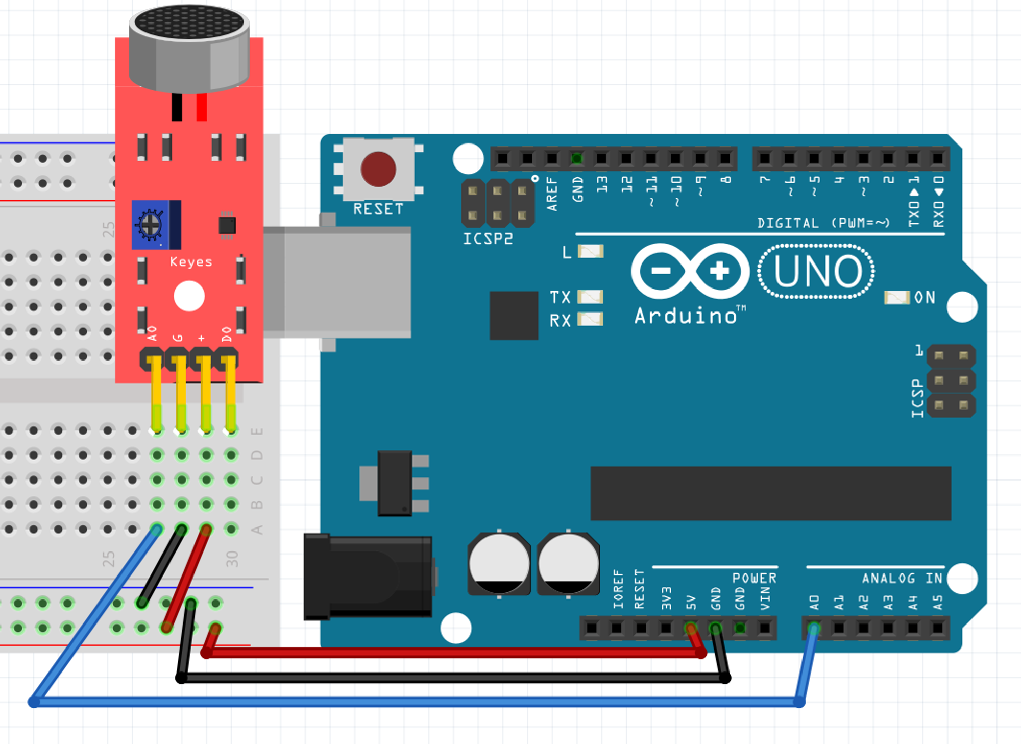
Hook up the A0 pin of the mic and print it in the console.
Circuit answer

optional content
void setup() {
  Serial.begin(9600);

    //remember, we don't have to setup an analog pin as input
    //because they can't do output, so they're always inputs
}

void loop() {
  Serial.println( analogRead(0) );
}
A cool trick you can do is instead of opening the “Serial monitor”, is to open the “Serial plotter”. This will give you a graph of the value with a self adjusting vertical axis. It’s very easy to use when you only pass one value to Serial.println and sometimes it's way clearer.