3 : The Breadboard
If you need to connect your component to a GND pin to flow current through them you might have noticed that the Arduino only have 3 of them, but 14 digital pins. Also it was very handy to have a digital pin next to a GND pin. How could we use more than 3 components? How do we plug component if the corresponding pins are not all neighbors?
The breadboard!

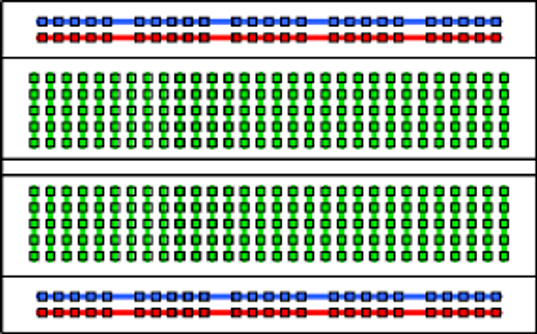
What is interesting is that the holes are the same size as the ones on the Arduino and they are connected together.
The red and blue lines have their holes connected length-wise while the rest are connected width-wise. Like this ⬇️

This means that if I use a wire to connect a GND pin of my Arduino to a blue line then all the things I will plug on the blue lines will be connected to the Arduino’s GND pin.
Exercise 5
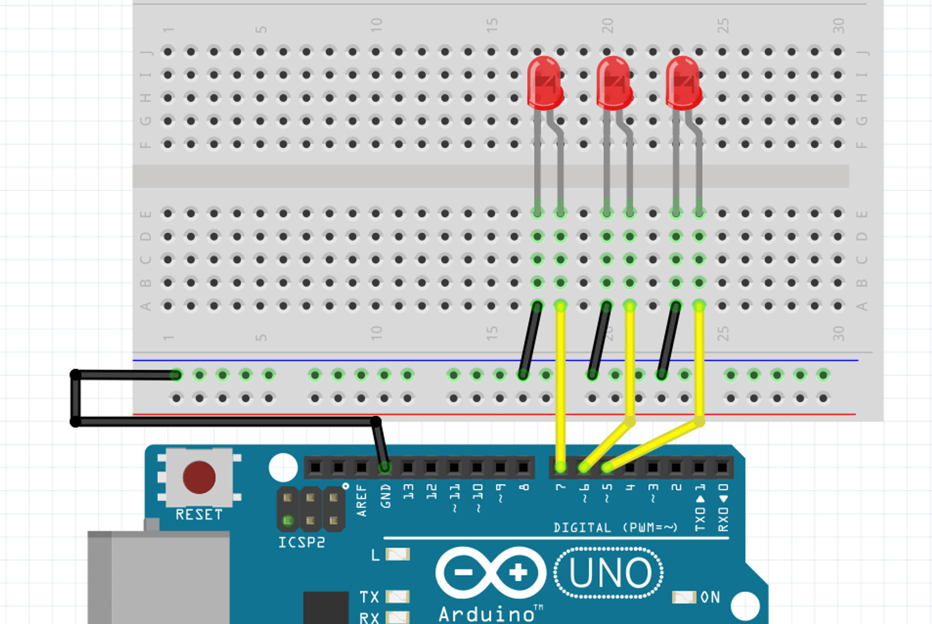
Can you blink 3 LEDs (however you want) while using only one GND pin on your Arduino?
answer

- Can you blink 3 LEDs (however you want) while using only one GND pin on your Arduino?
- Can you blink 3 LEDs (however you want) while using only one GND pin on your Arduino?
- Can you blink 3 LEDs (however you want) while using only one GND pin on your Arduino?
- No, you dont’ have to, but this is a convention followed by most people. The blue line has been drawn to suggest using it as GND. The red line is there to suggest using it as a common source of current (if you have one, right now we want to power our LED individually, so we need to power them with individual digital pins)
- Does the color of your wires matter?
- No, but it’s again, following general conventions makes it easier to re-read your circuit or help someone help you. By using warm colors for current sources and black/cold colors for current drains. But don’t stress it for the exercises, we might not have enough wire to enable everybody to wire it clean. But do care about it when you’re making a prototype.
Here is some code that works with the circuit above, feel free to light them up in a different way.
void setup() {
  pinMode(5, OUTPUT);
  pinMode(6, OUTPUT);
  pinMode(7, OUTPUT);
}

void loop() {
    digitalWrite(5,LOW);
    digitalWrite(6,HIGH);
    digitalWrite(7,LOW);

    delay(500);

    digitalWrite(5,HIGH);
    digitalWrite(6,LOW);
    digitalWrite(7,HIGH);

    delay(500);
}
Optionnal exercise
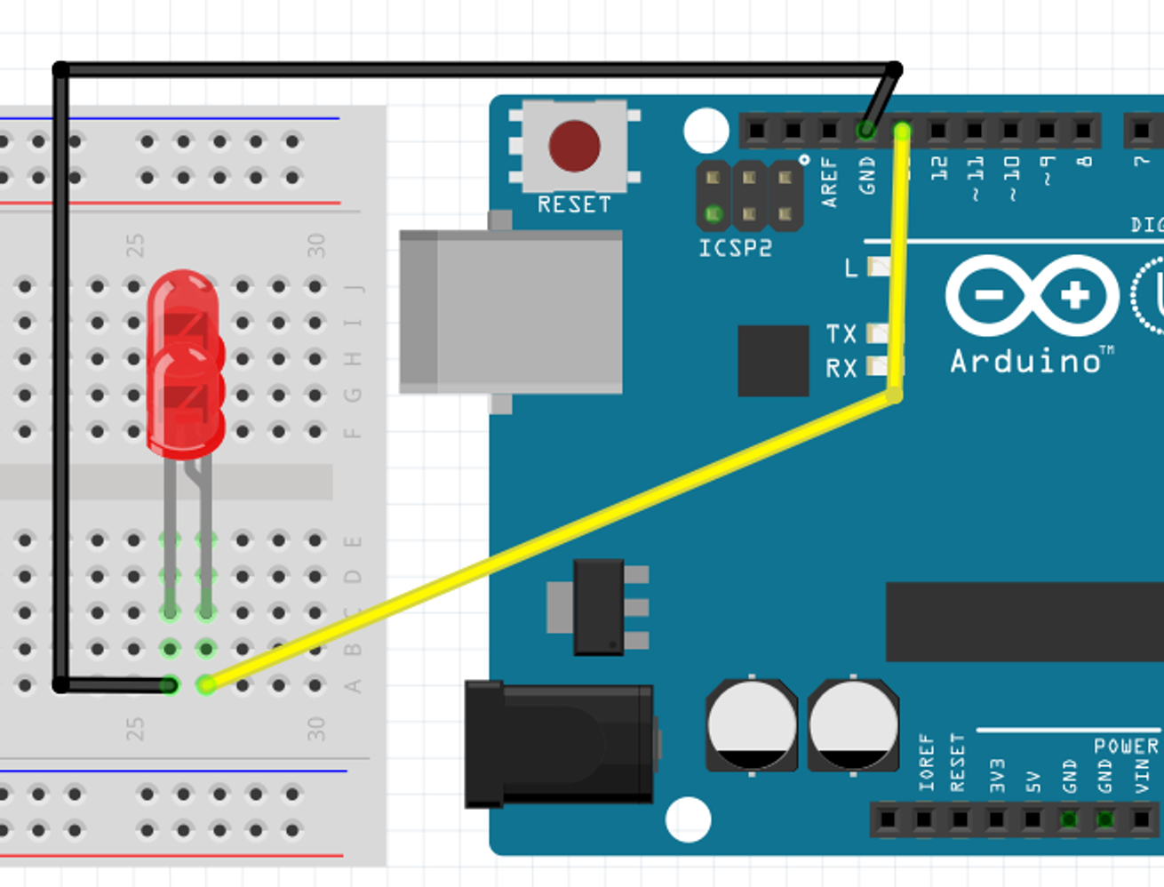
What would be the circuit to control 3 LEDs with only one digital pin and one ground pin?
answer

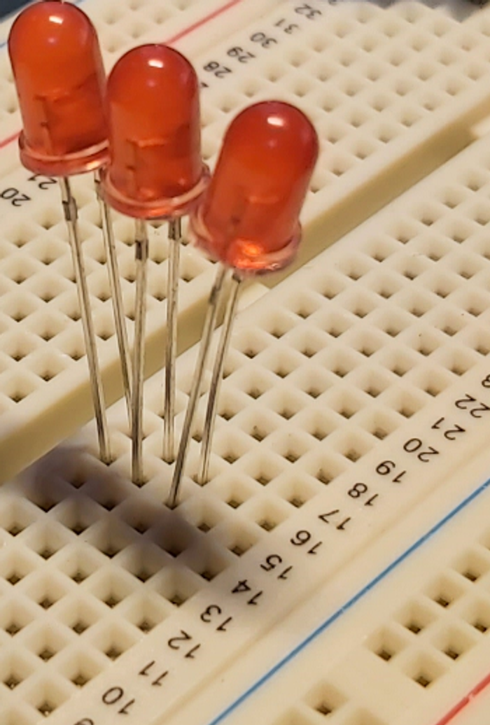
It doesn’t show very well on the drawing, but all 3 LEDs have their long legs together on one column and their short legs on the same column, like this ⬇️

Does it matter which GND pin you use on the Arduino?
Absolutely not. They’re all linked inside of the Arduino anyway.