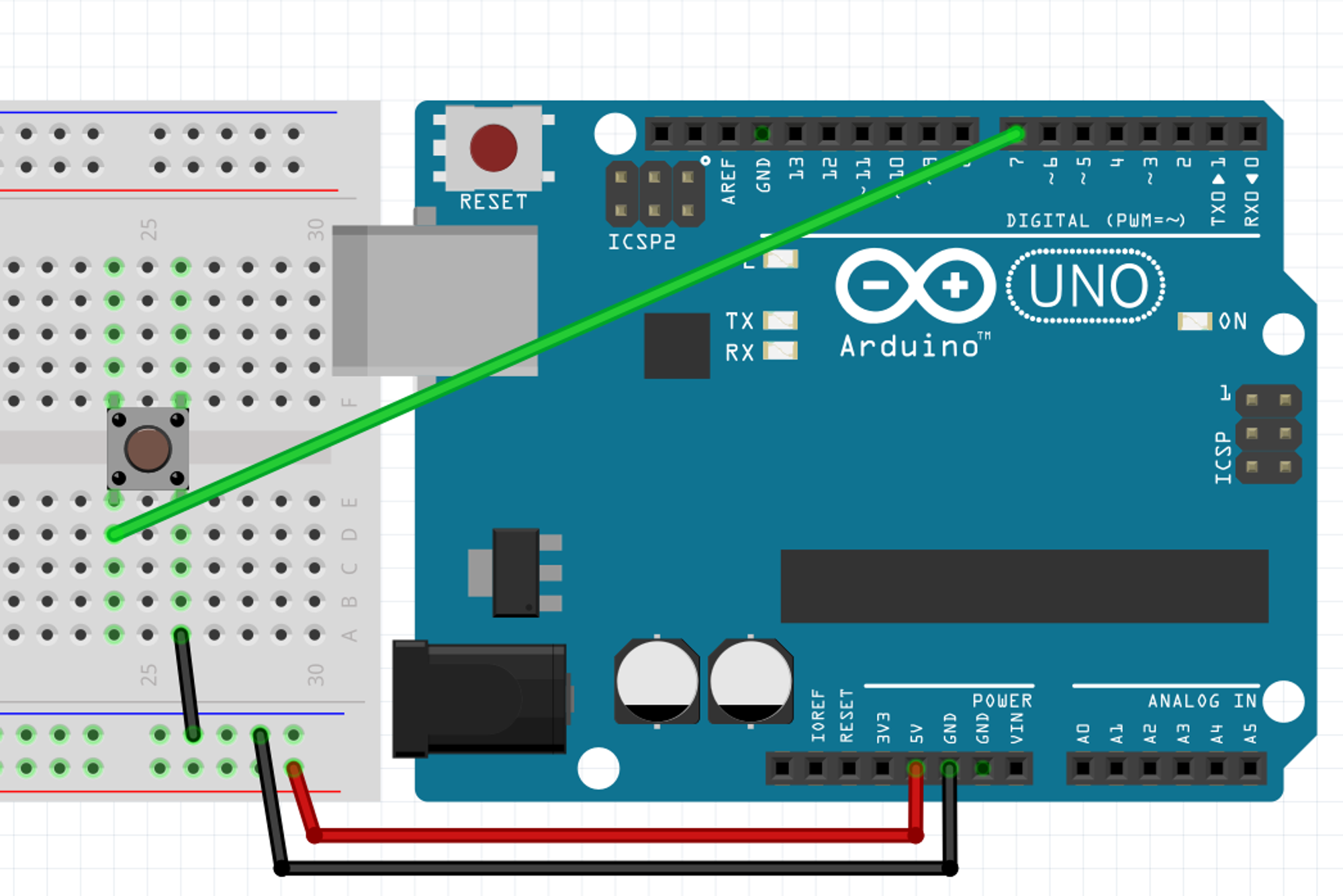
4 : The Button
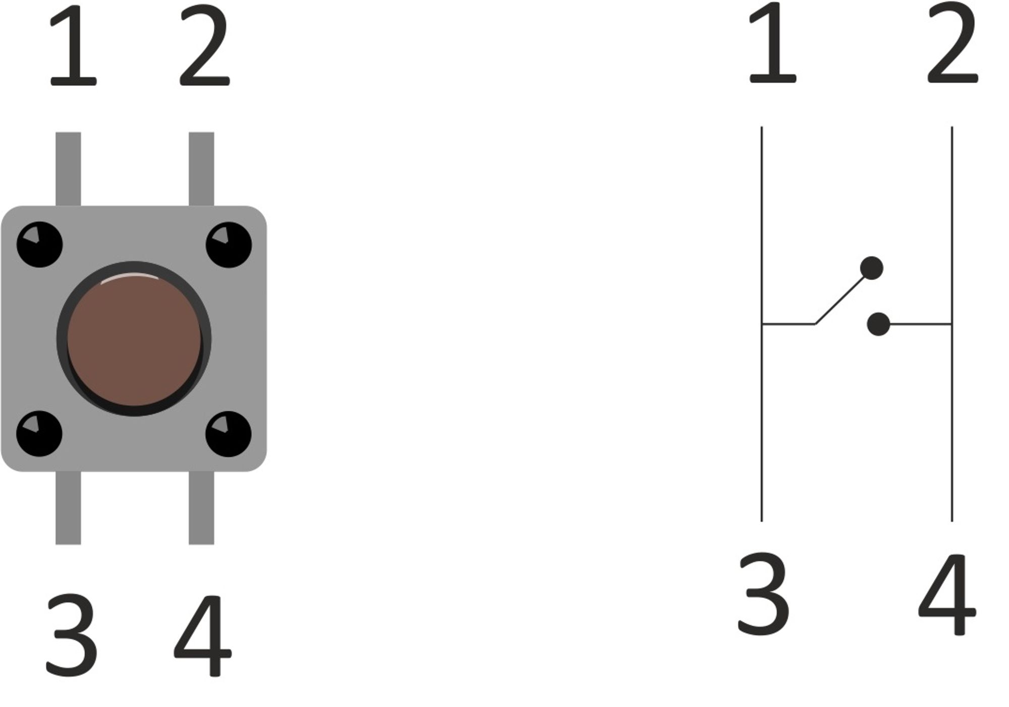
Here is a button and its insides, when the button isn’t pressed 1 and 3 are connected, 2 and 4 are connected. When the button is pressed all 4 pins are connected together.
Exercise 6
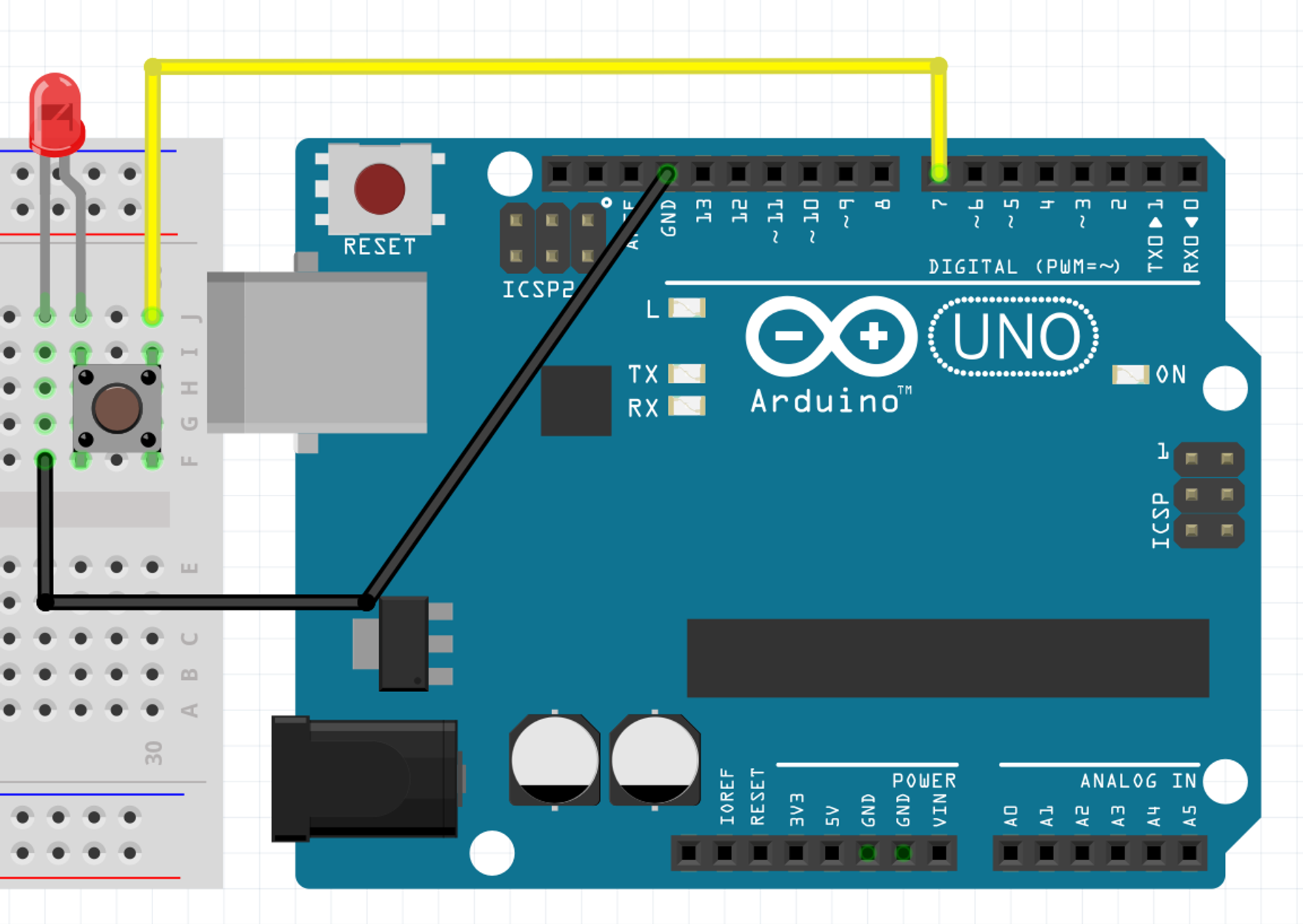
Now that we know the internal of a button and that digitalWrite enables us to send current suitable for an LED through a digital pin. Can you come up with a circuit and code to have an LED light up when the button is pressed? It doesn’t stay on when you release the button.
answer
void setup() {
  Serial.begin(9600);
  pinMode(7, OUTPUT);//config the pin to send current
    digitalWrite(7, HIGH);//just always send current
    //it will only flow if it finds a passage to GND anyways
    //...which is when the button is pressed
}

void loop() {}
What you’ve seen in the precedent exercise was a very “circuit” oriented approach, it works but usually we do it in a “code” oriented way. In the code oriented way you use an instruction to know if there is current on a digital pin and then you execute some code based on wether there was current or not.
Remember when we saw pinMode we mentioned the existence of the OUTPUT mode and the INPUT mode, well ...
There is one pinMode I haven’t told you about, it was added after the initial release of the Arduino platform, it’s not mandatory to understand how it works to use it, and it makes the button easy. If you want to know more, you’ll find a big collapsible bloc which will tell you more about buttons, the “classic” way to use them and how this pinMode works.
It is the INPUT_PULLUP mode.
pinMode(7, INPUT_PULLUP);
With this, the pin will always have tension, unless it is connected to the ground.
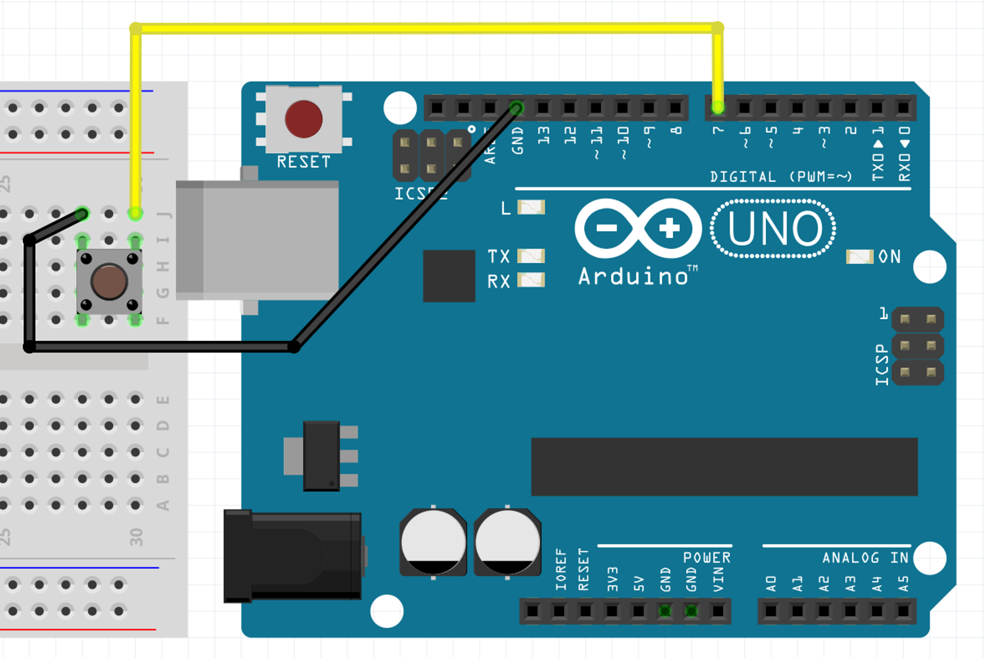
So if we wire it that way, we will have tension on the pin 7 until the button is pressed, because it will connect to the GND pin.
If digitalWrite() is the instruction to turn on a digital pin on or off (i.e. have tension or not), can you guess the instruction do look for tension on a digital pin?
digitalRead(7);
In this example the instruction will read the 7th pin and .... wait where is its answer!?
Well, this is one of the hard concept in the beginning. So far we have only seen commands which do things and that’s it. A command which “returns” a value will be replaced by the value once it is executed. You could look like digitalRead(7) as a value which is unknown for the moment and once it has been done it will either have the value of 1 or 0, “tension” or “no tension”.
Our “input pull-up” pin will always have tension as long as the button is not pressed, so in this case you can think of these two lines as doing the same thing.
//we just send 1 to the computer
Serial.println(1);

//The Arduino cannot send an unknown value so it will first look or current on pin 7
//which will turn digitalRead(7) into "1" and then send that 1 to the computer
Serial.println( digitalRead(7) );
Try the circuit above with just the button along with the code below and your monitor opened. What happens when you press the button?
void setup() {
  Serial.begin(9600);
  pinMode(7, INPUT_PULLUP);
}

void loop() {
  Serial.println( digitalRead(7) );
}
In programming there is something really fundamental called the “if statement”, it looks like this
if( a_condition ){
    //we do the code here if the condition is met
}
if the condition between the parentheses () is met then we execute the code which is between the curly braces {}.
A very useful thing is that we can complement an “if statement” with an “else statement” like this
if( a_condition ){
    //we do the code here if the condition is met
}else{
    //but if the condition is not met we do the code here instead
}
the else bloc contained by the following curly braces {} will only be executed if the condition wasn’t met, you can see it as an “alternative”.
Given all this information I could keep the circuit we have but use the code below instead.
void setup() {
  Serial.begin(9600);
  pinMode(7, INPUT_PULLUP);
}

void loop() {
  if( digitalRead(7) == 1 ){
        Serial.println("Nuit");
    }else{
        Serial.println("Jour");
    }
}
Try it. What do you see in the monitor?
Exercise 7
Can you use an “if statement” to turn on a LED when the button is pressed? The button and the LED will need separate digital pins. You can use the circuit on the last diagram to wire the button.
answer
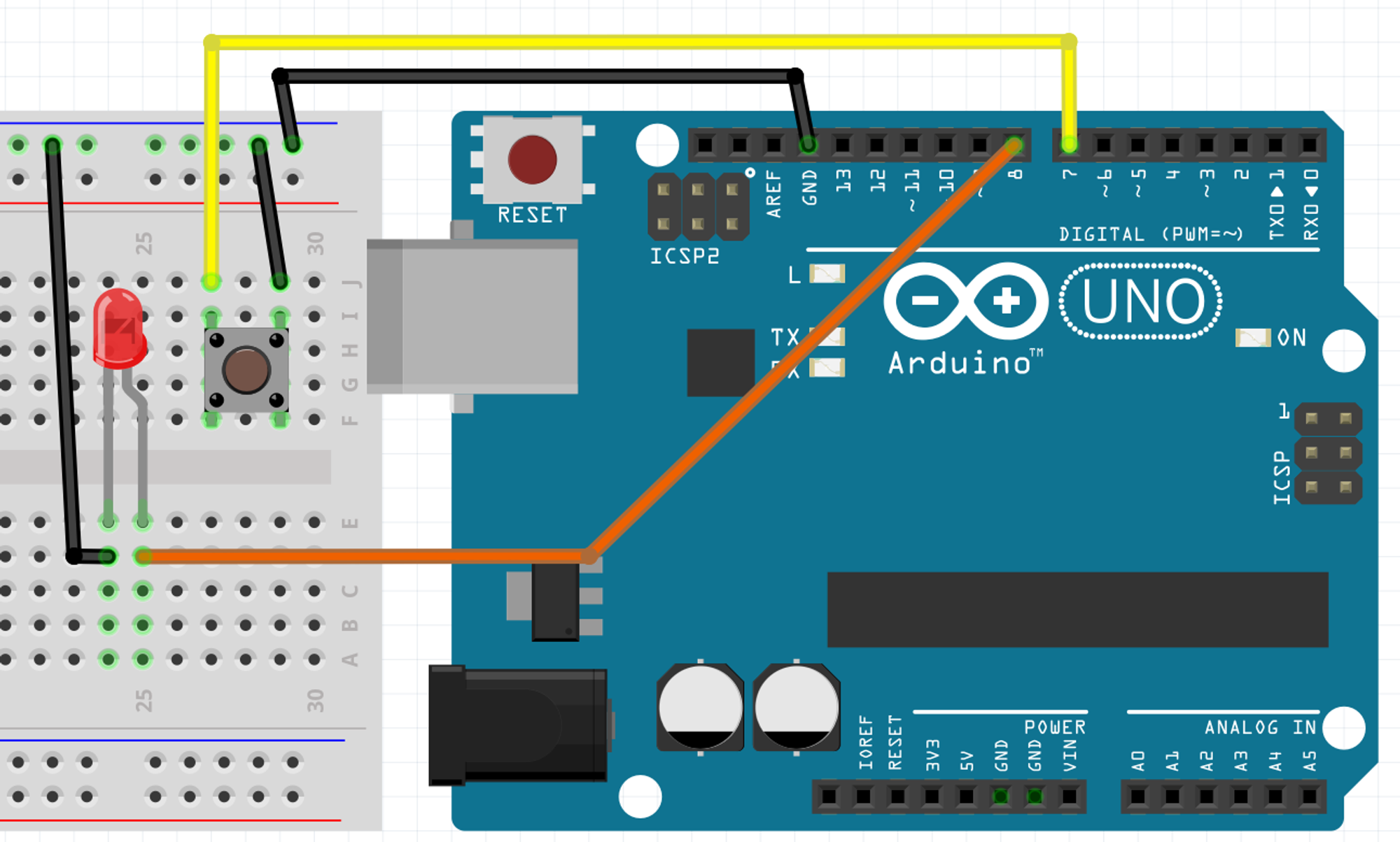
void setup() {
  Serial.begin(9600);

  pinMode(7, INPUT_PULLUP);//we'll be reading the button's tension via pin 7,remember that tension on the pin means "not pressed"
  pinMode(8, OUTPUT);//we'll light up or not the LED through pin 8
}

void loop() {
  if( digitalRead(7) == 1){//if the reading on digital pin 7 shows tension...
    digitalWrite(8,LOW);// ... we turn the pin 8 off
  }else{//... but if it doesn't...
    digitalWrite(8,HIGH);//... we turn the pin 8 on
  }
}
This solution is way more involved than the first one! Why bother? “Turning on the LED” was a very convenient use case, the “circuit” way and works only when you want something to receive* electricity when the button is pressed. If you want to do anything else the “code” approach is the way to do it. An example would be “rapidly flash the LED on and off while the button is pressed”, that would be way tougher to do it “circuit” way, at least it would be beyond the scope of this course.
*: or stop receiving but we didn’t see that one
Exercise 7.1
Rapidly flash the LED on and off while the button is pressed
answer
Same circuit as exercise 7
//same circuit usually means same setup
void setup() {
  Serial.begin(9600);

  pinMode(7, INPUT_PULLUP);//remember, because of "PULLUP" there is tension in the pin when it's "not pressed"
  pinMode(8, OUTPUT);
}

void loop() {
  if( digitalRead(7) == 1){//if the reading on digital pin 7 shows tension...
      digitalWrite(8,LOW);//... we turn the pin 8 off
  }else{//... but if it doesn't...
      digitalWrite(8,HIGH);//... we turn the pin 8 on
      delay(100);//wait for a bit
    digitalWrite(8,LOW);//then off
      delay(100);//this one is still important, part of flashing is also being down for a bit
  }
}
everything (else) about the button
pinMode(7,INPUT);
This will enable you to know if there is current or not.
One thing to understand is that parts of the circuits which has “tension” (a.k.a. “volts”) will seek to flow that tension to the “ground”. The current will flow through the path with the least resistance. The “5v” in of the Arduino cannot be controlled via code it just always have 5 volts of tension so if we have the circuit below.
⚠️ DO NOT REPRODUCE THIS ONE ⚠️
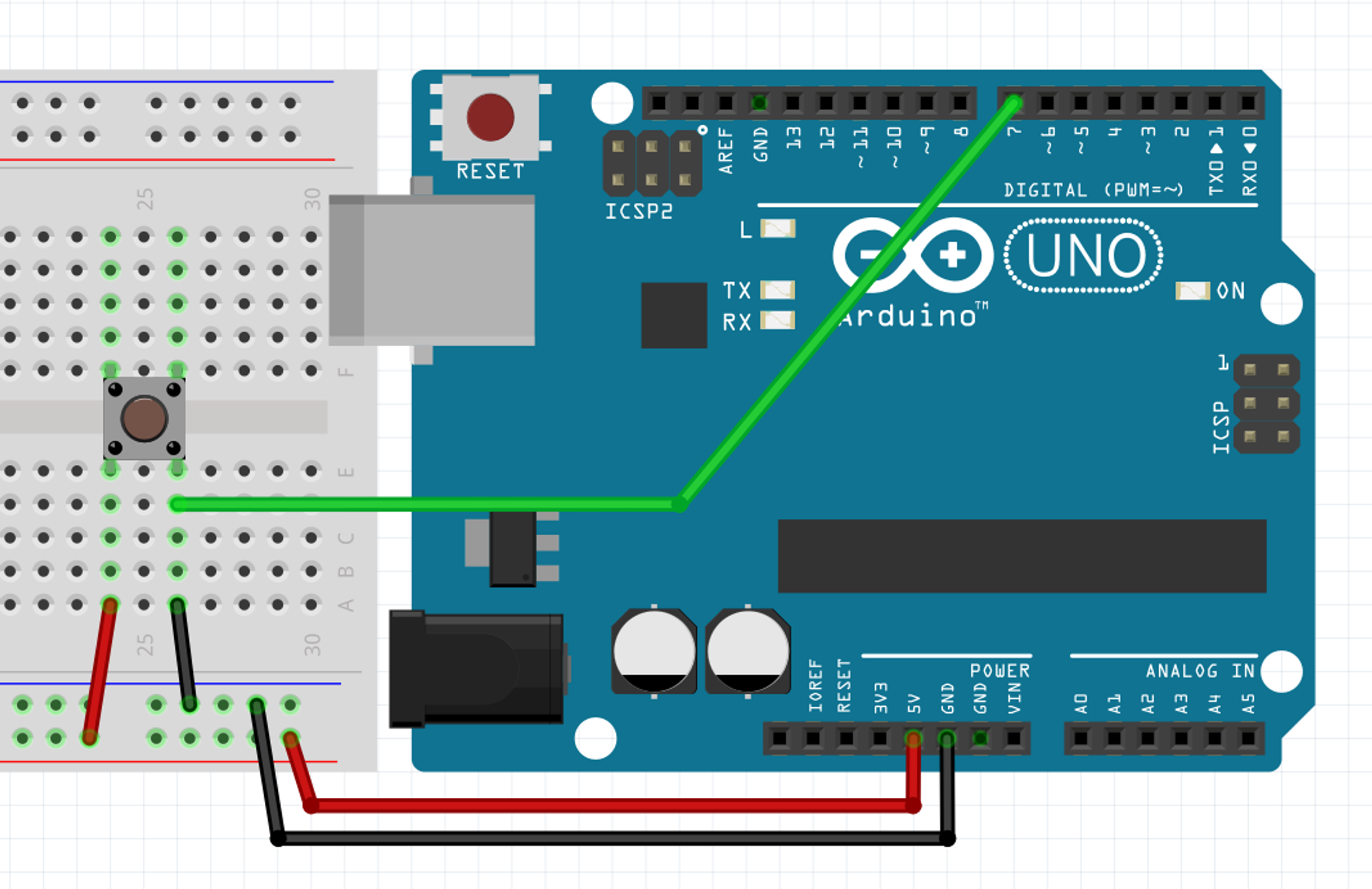
Sure, the tension from the 5V pin will flow into the ground when the button is pressed but if there is nothing to slow down the flow from the 5V to the GND, that’s called a short circuit and that’s very damaging to your electronics (thankfully the Arduino Uno is protected and will “just” turn off when a short circuit is detected).
Sure, the tension from the 5V pin will flow into the ground when the button is pressed but if there is nothing to slow down the flow from the 5V to the GND, that’s called a short circuit and that’s very damaging to your electronics (thankfully the Arduino Uno is protected and will “just” turn off when a short circuit is detected).
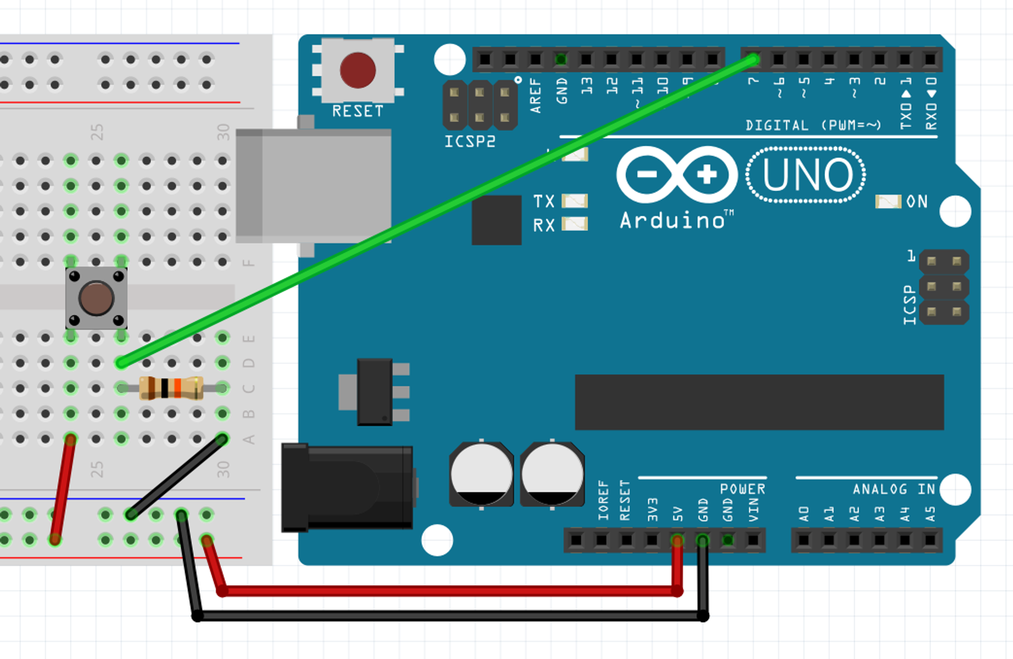
This way the current can safely flow the current from the 5V to the GND pin while sensing it with the 7th digital pin. You can try it with the code below (which has been compacted because there is nothing new, just paste it in.)
void setup() {Serial.begin(9600);}
void loop() {Serial.println(digitalRead(7));}
But remember, we had to put a resistor between 5V and GND, above we chose to put it on the GND pin, we could have put it on the 5V pin like this
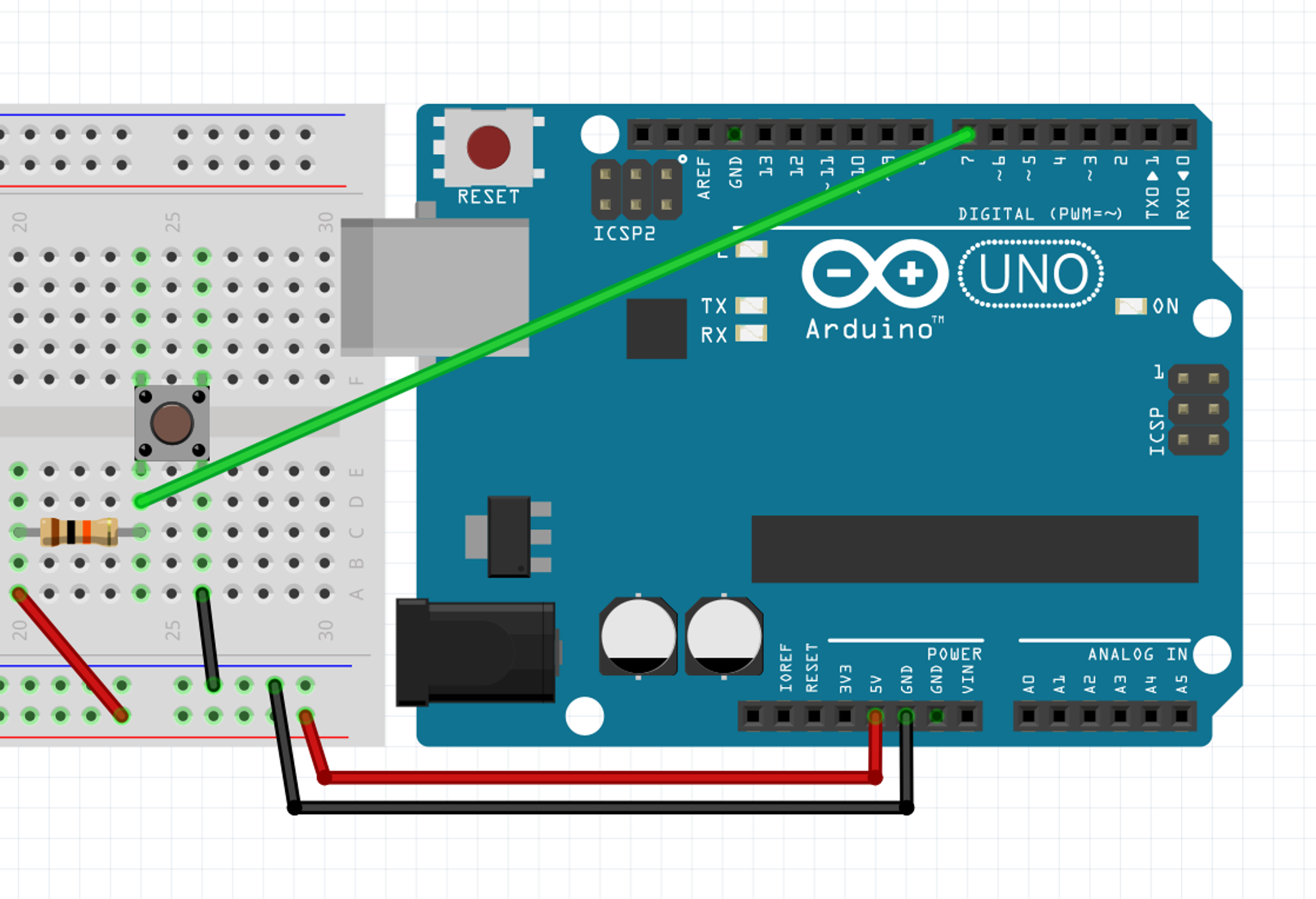
Try it with the same code. Do you notice anything?
Exactly, that’s the same behavior as when we used INPUT_PULLUP, we get 0 when the button is pressed and 1 otherwise. When the resistor is on the GND pin we call it a “pull down” resistor, while we call it a “pull up” resistor when it’s on the 5V pin. Using INPUT_PULLUP wires the 5V and a resistor internal to the Arduino to a digital pin allowing you to simplifying the circuit above into the one below.
